 Pipe Industry Co., Ltd.")

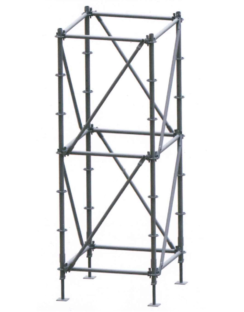
60 series construction method
1. Under the care
After setting out according to the size of the scaffolding configuration diagram, arrange the 【Lower Support】to the fixed point.
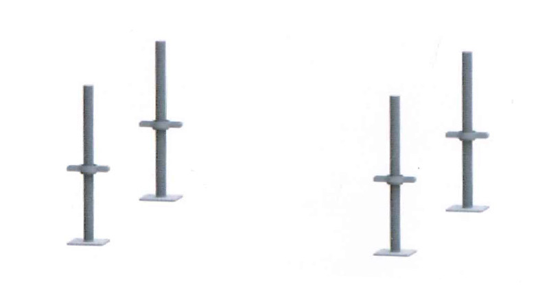
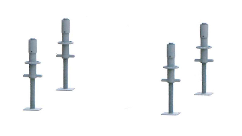
2. Standard base:
Put the main frame sleeve part of the [standard base] above the lower support screw, and the lower edge of the standard base should be completely inserted into the groove of the wrench force plane.
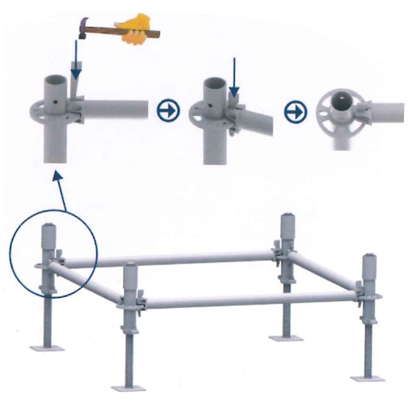
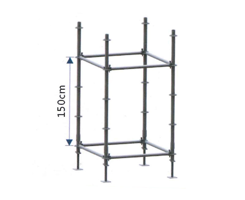
3. First layer crossbar:
Put the cross rod head into the small hole of the disc, so that the front end of the cross rod head is against the vertical rod tube, and then use a wedge pin to penetrate the small hole to fasten it.
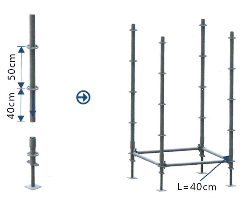
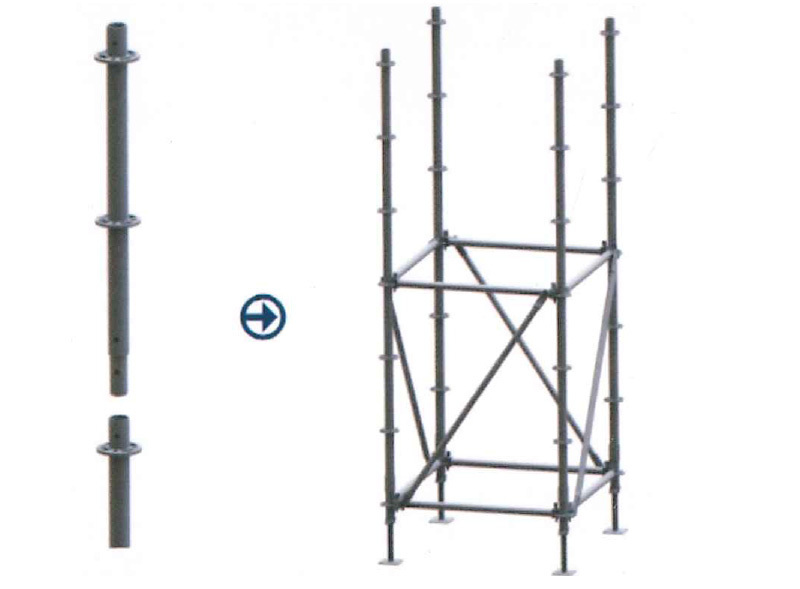
4. Starting pole:
The poles that are not installed (connecting rods) are collectively referred to as "starting poles". Insert the long ends of the "starting poles" into the sleeves of the standard base as shown in the figure below. Check the position of the inspection hole to see if the "starting pole" is inserted into the bottom of the sleeve. The "starting pole" is only applicable to the lap joint on the first layer, and the "butt pole" is applicable to the second layer upwards.
5. The second floor crossbar:
As shown in the figure below, install the second-layer crossbar according to step 3.
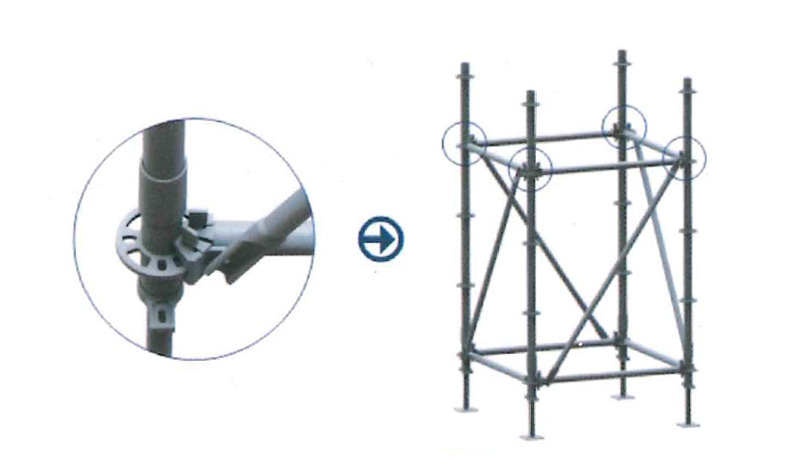
6. The first layer of diagonal tie rods:
Assemble all the [tilt rods] clockwise or all counterclockwise, as shown in the figure below, insert the [tilt rod] into the position of the large hole of the disc, so that the front end of the inclined rod head is against the main frame tube, and then use the inclined rod Wedge through the large hole to tap and fix. (Note: The tie rods are directional and cannot be built in the opposite direction)
7. Docking pole:
The "butt pole" is connected by a square tube (connecting rod), as shown in the figure below, insert the connecting rod into the lower tube.
※If you need to apply the "docking pole latch", be sure to check whether the disc alignment holes are in the same direction.
8. The third floor crossbar:
"At the location as shown in the figure below, follow step 3 to install the third-layer crossbar.
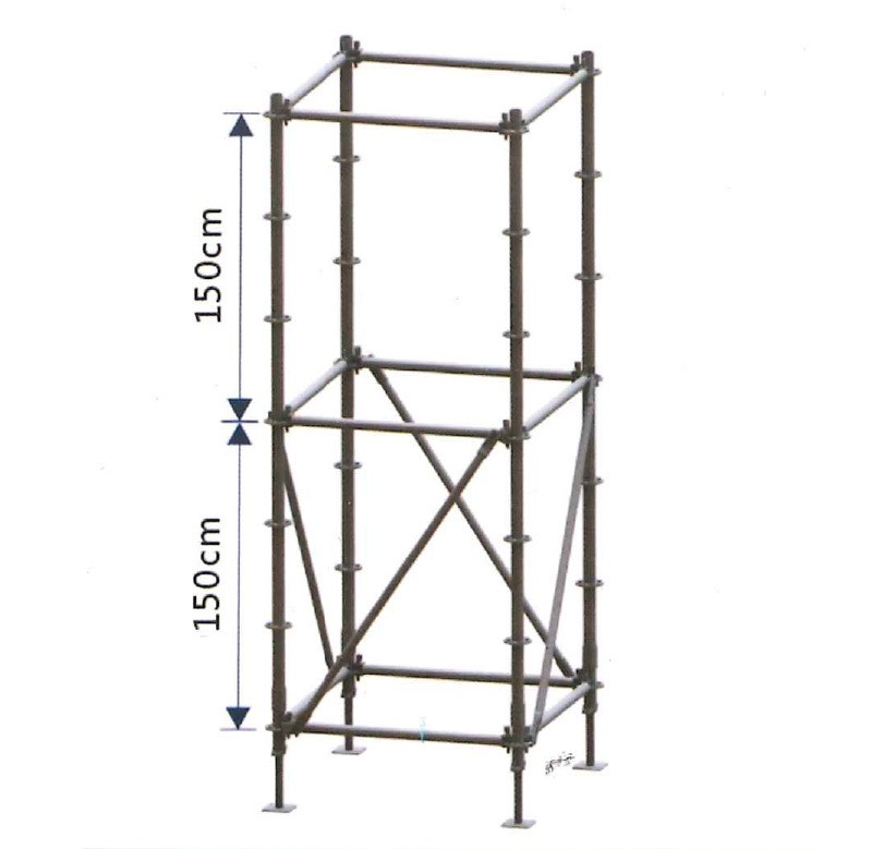
9. The second layer of tie rods:
As shown in the figure below, according to step 6, lap the second layer in the same direction as the first layer.
※If the first layer is assembled in a counter-clockwise direction, the diagonal tie rods above the second layer also need to be assembled in a counter-clockwise direction
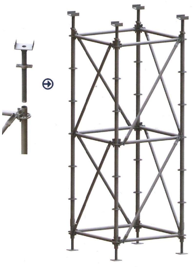
10. Support:
Insert the "top bracket" dental tube into the vertical rod tube as shown in the figure below, and then adjust it to the desired height with a wrench.

Address:
Industrial Cluster Area, Qi County, Hebi City, Henan Province
Tel:
+86-392-6500228 +86-137-93116338
Mail:
Follow us


